|
|

|
 |
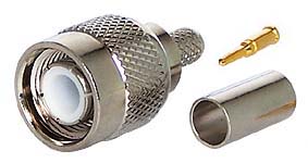
TNC series connectors
are designed as a threaded version of the BNC, the
TNC series features screw threads for mating. TNC
are miniature, threaded weatherproof units with
constant 50 Ω impedance and they operate from 0
- 11 GHz.
There are two types of TNC connectors: Standard
and Reverse Polarity. Reverse polarity is a keying
system accomplished with a reverse interface, and
ensures that reverse polarity interface connectors
do not mate with standard interface connectors.
Cable terminations are available in crimp , clamp,
twist-on and solder configurations. The 7/16"-28
thread coupling provides positive mating.
Although their rugged design was initially developed
for shock and high vibration environments, TNC connectors
are widely accepted and used for data transmission,
medical equipment, cellular mobile telephones, test
equipment, microwave components and aerospace applications. |
|
|
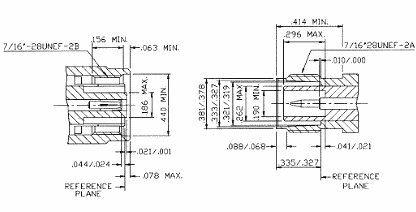
| • Interface
Dimensions |
|
PLUG
| Letter |
Millimeters(Inches) |
| Minimum |
Maximum |
| A |
2.06(.081) |
2.21(.087) |
| B |
1.32(.052) |
1.37(.054) |
| C |
4.83(.190) |
— |
| D |
SLOTTED
AND FLARED TO
MEET ELECTRICAL AND
MECHANICAL REQUIREMENTS |
| E |
11.18(.440) |
— |
| F |
0.15(.006) |
— |
| G |
— |
1.98(.078) |
| H |
5.28(.208) |
5.79(.228) |
| I |
5.33(.210) |
— |
| J |
0.08(.003) |
1.02(.040) |
| K |
1.60(.063) |
— |
| L |
3.96(.156) |
— |
| M |
1.98(.078) |
— |
|
JACK
| Letter |
Millimeters(Inches) |
| Minimum |
Maximum |
| A |
— |
4.72(.186) |
| B |
8.10(.319) |
8.15(.321) |
| C |
8.31(.327) |
8.46(.333) |
| D |
9.60(.378) |
9.68(.381) |
| E |
1.73(.068) |
2.24(.088) |
| F |
8.31(.327) |
8.51(.335) |
| G |
10.52(.414) |
— |
| H |
4.75(.187) |
— |
| I |
— |
0.15(.006) |
| J |
4.72(.186) |
5.23(.206) |
| K |
4.95(.195) |
— |
| L |
4.78(.188) |
5.28(.208) |
|
|
| Electrical: |
| Impedance |
50 ohm |
75 ohm |
| Frequency Range |
0 to 11.0 GHz |
0 to 1.0 GHz |
| VSWR |
Straight : 1.3 max ; Right Angle : 1.35
max |
| Working Voltage |
500 volts rms max at sea level |
| Dielectric Withstanding
Voltage |
1,500 volts rms max at sea level |
| Contact Resistance |
center contact=1.5 Milliohms max
outer contact=1.0 Milliohms max |
| Insertion Loss |
0.2 dB max @ 3 GHz |
| Insulation Resistance |
5,000 Megohms min |
|
| |
| Mechanical
& Environmental: |
| Mating |
7/16"-28 threaded coupling |
| Cable Retention |
RG-58,141,142,223 →40 lbs min
RG-59,62A,210→40 lbs min
RG-174,188,316 →20 lbs min |
| Durability |
500 matings |
| Coupling Nut Retention |
100 lbs min |
| Temperature Range |
-65°C to 165°C |
| Vibration |
MIL-STD-202 Method 204 Test Cond. B. |
| Salt Spray |
MIL-STD-202 Method 101 Test Cond. B. |
| Thermal shock |
MIL-STD-202 Method 107 Test Cond. B. |
|
| |
| Materials
/ Finish: |
| |
Material |
Plating |
| Connector Body |
Brass |
Nickel or Silver |
| Center Contact |
Male:Brass
Female :Brass,
Phosphor Bronze or
Beryllium Copper |
Gold
Gold |
| Insulation |
Teflon or Delrin |
None |
| Gasket |
Silicone Rubber, Rubber |
None |
| Crimp Ferule |
Annealed Copper |
Same as Body |
|
| |
| Reverse
Polarity TNC: |
 |
| Electrical : |
| Impedance |
TNC:50 ohm |
| Frequency Range |
TNC:0-11GHz |
| VSWR |
1.3max (Straight); 1.35 max (Right Angle) |
| Voltage Rating |
500 volts rms max |
| Dielectric Withstanding
Voltage |
1,500 volts rms |
| Insertion Loss |
0.2 dB max @ 3 GHz; |
| Insulation Resistance |
5,000 Megohms min |
|
| Mechanical
& Environmental: |
| Mating |
TNC:7/16"-28 thread coupling |
| Durability |
500 matings |
| Coupling Nut Retention |
100 lbs Min |
| Cable Retention |
RG-58,141,142,223→40 lbs min;RG-59,62A,210→40lbs min;
RG-174,188,316→20 lbs min |
| Thermal shock |
-65°C to 165°C |
|
| Materials
/ Finish: |
| |
Material |
Plating |
| Connector Body |
Brass |
Nickel or Gold |
| Center Contact |
Male:Brass
Female :Beryllium Copper |
50 µ " gold over 100 µ
" nickel |
| Insulation |
Teflon |
None |
| Gasket |
Silicone Rubber, Rubber |
None |
| Crimp Ferule |
Annealed Copper |
Same as Body |
|
|
|