|
|
 |
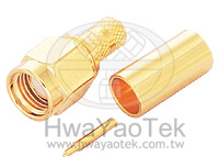
| SMA connectors are semi-precision,
subminiature devices that provide repeatable electrical
performance from DC to 12.4 GHz with flexible cable.
These devices offer broadband performance with low
reflection and constant 50 ohm impedance. These
|
|
| properties,
along with minimum attenuation and low VSWR have made
the SMA extremely popular in the microwave community.
The SMA design has been broadened to accommodate many
interconnect requirements and is available in pressure
crimp, clamp and solder terminal attachments. SMA design
parameters have incorporated the considerations of balancing
cost, size, weight and performance to yield the best value
in your microwave system. Among typical applications are
components such as dividers, mixers, amplifiers, trimmers
and attenuators. SMA connectors are also used to provide
interconnections from printed circuit board stripliness
to coaxial cable.SMA is available both in Standard and
Reverse Polarity. Reverse polarity is a keying system
accomplished with a reverse interface, and ensures that
reverse polarity interface connectors do not mate with
standard interface connectors. |
|
• Interface
Dimensions |
|
|
PLUG
| Letter |
Millimeters(Inches) |
| Minimum |
Maximum |
| A |
0.00(.000) |
0.38(.015) |
| B |
0.90(.0355) |
0.94(.037) |
| C |
— |
4.59(.1808) |
| D |
6.35(.250) |
— |
| E |
0.00(.000) |
0.18(.007) |
| F |
0.00(.000) |
0.25(.010) |
| G |
— |
2.54(.100) |
| H |
— |
3.43(.135) |
|
JACK
| Letter |
Millimeters(Inches) |
| Minimum |
Maximum |
| A |
4.60(.1810) |
4.67(.1837) |
| B |
5.28(.208) |
5.49(.216) |
| C |
0.00(.000) |
0.18(.007) |
| D |
0.00(.000) |
0.25(.010) |
| E |
2.92(.115) |
— |
| F |
1.88(.074) |
1.98(.078) |
| G |
0.38(.015) |
1.149.045) |
| H |
4.32(.170) |
— |
| I |
5.54(.218) |
— |
| J |
1.24(.049) |
1.30(.051) |
|
|
| Electrical: |
| Impedance |
50 ohm |
| Frequency Range |
0 to 12.0 GHz
• for flexible cable→max operation frequency of
cable per MIL-C-17 (12.4 GHz maz) |
| VSWR |
| RG178U→ |
1.2+0.025 f max (Straight)
1.2+0.03 f max (Right Angle) |
| RG316U→ |
1.15+0.02 f max (Straight)
1.15+0.03 f max (Right Angle) |
| RG142U→ |
1.15+0.01f max (Straight)
1.15+0.02 f max (Right Angle) |
|
| Working Voltage |
• RG-58,141,142,223→500 volts rms
max
•
RG-174,188,316→335 volts rms max
• RG-178,196→250
volts rms max |
| Dielectric Withstanding
Voltage |
• RG-58,141,142,223→1,000 volts
rms max
•
RG-174,188,316→750 volts rms max
• RG-178,196→500
volts rms max |
| Contact Resistance |
center contact=3.0 Milliohms
max
outer contact=2.0 Milliohms max |
| Insertion Loss |
0.06 dB max × 1.5 GHz @ 6 GHz |
| Insulation Resistance |
5,000 Megohms min |
|
| |
| Mechanical
& Environmental: |
| Mating |
1/4"-36 threaded coupling |
| Durability |
500 matings |
| Coupling Nut Retention |
60 lbs Min |
| Recommend Nut Mating Torque |
7 to 10 inch-pounds |
| Cable Retention |
RG-58,141,142,223→40 lbs min
RG-174,188,316 →20 lbs min |
| Temperature Range |
-65°C to 165°C |
| Vibration |
MIL-STD-202 Method 204 Test Cond. D. |
| Salt Spray |
MIL-STD-202 Method 101 Test Cond. B. |
| Thermal shock |
MIL-STD-202 Method 107 Test Cond. B. |
|
| |
| Materials
/ Finish: |
| |
Material |
Plating |
| Connector Body |
Brass |
Nickel or gold |
| Center Contact |
Male:Brass
Female:Beryllium Copper |
30µ " gold over 100 µ " nickel
30µ " gold over 100 µ " nickel |
| Insulation |
Teflon |
None |
| Gasket |
Silicone Rubber |
None |
| Crimp Ferule |
Annealed Copper |
Same as Body |
|
|
|
| Reverse Polarity
SMA : |
 |
| Electrical : |
| Impedance |
50 ohm |
| Frequency Range |
0 to 12 GHz
• for flexible cable→max operation frequency of cable
per MIL-C-17(12.4GHz max) |
| VSWR |
| RG178U→ |
1.2+0.025 f GHz max(Straight)
1.2+0.03 f GHz max(Right Angle) |
| RG316U→ |
1.15+0.02 f GHz max
(Straight)
1.15+0.03 f GHz max (Right Angle) |
| RG142U→ |
1.15+0.01 f GHz max
(Straight)
1.15+0.02 f GHz max (Right Angle) |
|
| Working Voltage |
375 volts rms max |
| Dielectric Withstanding
Voltage |
100 volts rms |
| Insertion Loss |
0.06 dB maximum x??GHz@ 6GHz;
|
| Insulation Resistance |
5,000 Megohms min |
|
| Mechanical
& Environmental: |
| Mating |
1/4"-36 threaded coupling |
| Durability |
500 matings |
| Coupling Nut Retention |
60 lbs Min |
| Cable Retention |
RG-58,141,142,223→41 lbs min
RG-174,188,316→20lbs min |
| Thermal shock |
-65°C to 165°C |
|
| Materials
/ Finish: |
| |
Material |
Plating |
| Connector Body |
Brass |
Nickel or Gold |
| Center Contact |
Male:Brass
Female:Beryllium Copper |
30 µ " gold over 100 µ
" nickel |
| Insulation |
Teflon |
None |
| Gasket |
Silicone Rubber |
None |
| Crimp Ferule |
Annealed Copper |
Same as Body |
|
|
|